


Toshiba Automotive 3-Phase Brushless Motor Gate Driver IC
2025-03-13 17:47
Toshiba - Gate Driver IC Compliant with the Latest Functional Safety Standard
Suitable for 3-phase brushless DC motor applications such as Electric Power Steering (EPS) and Electric Braking Systems.
Product Highlights
·Built-in 3-channel safety relay driver IC
·Small VQFN48 package, reducing mounting area by approximately 66%[1](Verified to withstand 3,000 cycles in mounting temperature cycling tests)
·Built-in self-diagnostic circuit for external MOSFETs
The development of automotive equipment must comply with the ISO 26262 functional safety standard for road vehicles[2]. Of course, the semiconductor devices and other electronic components used in automotive equipment are no exception and must comply with this standard.
Toshiba Electronic Devices & Storage Corporation (“Toshiba”) launched an ISO 26262 compliant gate driver IC supporting ASIL-D safety and other extremes[4]for in-vehicle 3-phase brushless DC motors[3]– “TB9083FTG” [4]. This device drives external MOSFETs to rotate a 3-phase brushless DC motor (Figure 1), and can drive the upper and lower MOSFETs of all 3 phases, i.e., six MOSFETs. Application examples include Electric Power Steering (EPS), electric braking, and shift-by-wire systems.
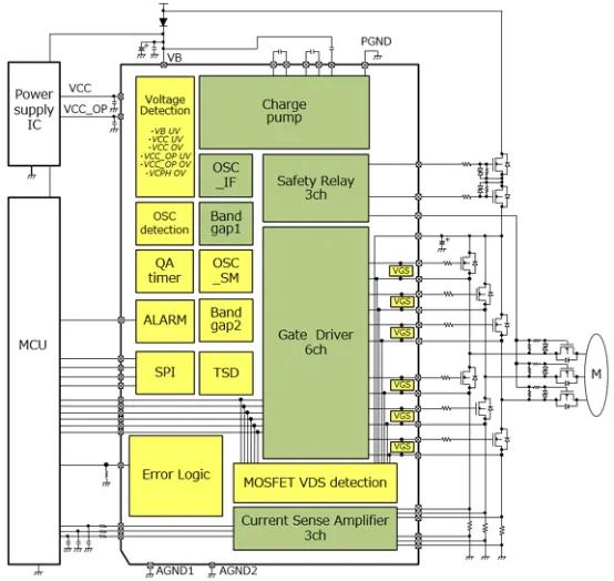
Figure 1: Internal block diagram and application circuit example
Toshiba previously released a gate driver IC compliant with ISO 26262, the “TB9081FG”, in August 2017. The TB9083FTG is an improved and upgraded product based on the “TB9081FG”.
The main improvements are the stability of functions achieved through redundancy, ABIST (Analog Built-In Self-Test), and LBIST (Logic Built-In Self-Test) circuits. These are essential for passing the ISO 26262 standard. In terms of functional redundancy, like the TB9081FG, the TB9083FTG has two built-in bandgap reference voltage circuits and two additional built-in clock oscillators (OSC). The purpose is to minimize the occurrence of related failures. On the other hand, ABIST and LBIST are responsible for checking whether the internal diagnostic functions are working properly. The check results can be read out via SPI communication.
Built-in 3-channel safety relay driver IC
The TB9083FTG has three major improvements. First, compared to the five channels of the TB9081, it only includes three channels for safety relays. Safety relays can achieve electrical disconnection in case of abnormalities such as motor or external MOSFET. Based on Customer Feedback, three channels are sufficient to meet system requirements. For EPS, two channels are used for the power relay and reverse polarity protection relay, respectively, and the other channel is used for the motor relay to cut off the motor control circuit. (Figure 2)
TB9083FTG Advantages (1)
Built-in redundant/non-redundant 3-channel relay driver IC
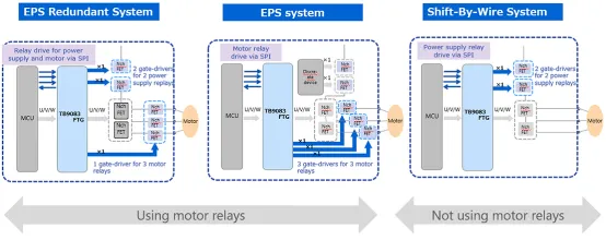
Figure 2: Example of using safety relays
Reduce mounting area with small package (up to 66%[1])
The second feature is the use of a VQFN 48-pin package (7.0mm×7.0mm) to reduce the PCB mounting area (Table 1). Since the TB9081FG uses a 64-LQFP package with a mounting area of 12.0mm×12.0mm (including external leads), the mounting area is reduced by about half in comparison. The choice of small package is closely related to ISO 26262 because ISO 26262 may require the use of redundant devices to ensure functional stability to achieve higher safety levels. With this redundant configuration, even if one TB9083FTG fails, another TB9083FTG can still drive the motor. However, using two devices would double the PCB mounting area. Therefore, TB9083FTG uses a small package to prevent increasing the mounting area.
TB9083FTG Advantages (2)
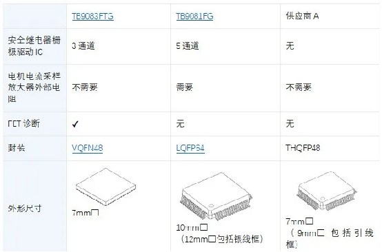
Table 1: Comparison of three devices
In addition, to further reduce the required PCB mounting area, the TB9083FTG also uses built-in resistors to adjust the gain and reference voltage of the motor current sampling amplifier. The TB9081FG requires these resistors to be configured externally. The gain can be set via the serial interface SPI.
Built-in External MOSFET Self-Diagnostic Circuit
The third feature is the built-in sequencer and verification circuit for detecting open and short circuit failures of external MOSFETs. TB9083 monitors the midpoint of each upper and lower arm in the 3 phases (Figure 3). The microcontroller reads out the diagnostic results via SPI. For this diagnosis, the TB9081FG needs to use the microcontroller's built-in A/D converter (ADC) and external bias resistors to monitor the motor terminal voltage. In addition to not needing to use the A/D converter in the microcontroller (MCU) for this diagnosis, another advantage is reducing the amount of software code and eliminating the external resistors required for diagnosis.
TB9083FTG Advantages (3)
Self-diagnostic circuit for external MOSFETs
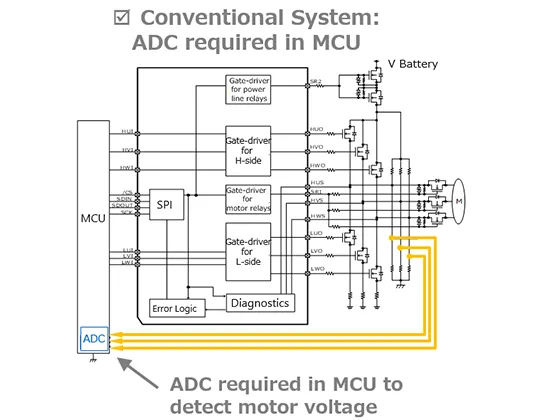
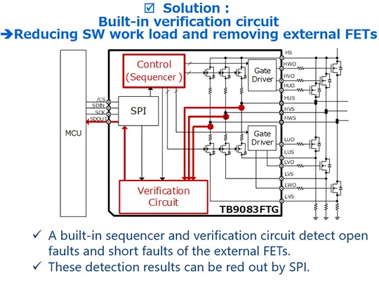
Figure 3: Comparison between traditional system and TB9083FTG solution
Verified to withstand 3,000 temperature cycle tests
QFN package uses solderable side wings[5]This makes it easy to visually inspect solder joints using an automatic optical inspection (AOI) system and helps improve solder joint reliability. In addition, Toshiba has verified that the package can withstand 3,000 cycles in mounting temperature cycle tests.
Passed 3,000 cycle test
| Category
|
Item
|
Test conditions
|
| Test Temperature
|
-40℃~125℃ |
|
| Failure Standard
|
Initial resistance drift 10%
|
|
| IC
|
Package
|
VQFN48-0707-0.50 (solderable side wings)
|
| Plating
|
Sn
|
|
| PCB
|
Size
|
35mm×35mm×1.6mmt
|
| Layers
|
6 layers
|
|
| Material
|
FR-4
|
|
| Surface Treatment
|
OSP (Organic Solderability Preservative)
|
|
| Welding
|
Solder
|
SAC305
|
| Shielding layer thickness
|
130um
|
|
| Peak temperature during reflow soldering process
|
230℃ to 250℃
|
|
| Welding between the E-pad of QFN and PCB
|
Execution
|
|
Table 2: Mounting temperature cycle test results and test conditions
Toshiba will continue to strengthen its gate driver IC product line that meets the requirements of version 2 of the ISO 26262 standard to support automotive three-phase brushless motor applications. Toshiba will continue to launch IC products with optimized functions and performance to meet customer needs and contribute to improving the electrification and safety of automotive equipment.
Note:
[1]Compared with Toshiba's existing product TB9081FG (12.0mm×12.0mm (typical value))
[2]A functional safety standard designed to minimize the risk of system failures. Importantly, it ensures a reasonable explanation of system safety is provided to third parties. ISO 26262 is a functional safety standard for automotive applications, specifying the development processes to ensure the achievement of the required functional safety.
[3]Driver IC used to drive MOSFET
[4]ASIL: Automotive Safety Integrity Level, D: Level D (A to D level, D being the highest level)
[5]The shape of the package's external leads
The above content is quoted from Toshiba's official website, URL: Automotive three-phase brushless motor gate driver IC: TB9083FTG | Toshiba Semiconductor & Storage Products China Official Website
The main Toshiba Mosfet models promoted in the automotive application field are as follows:
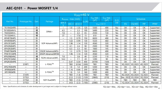
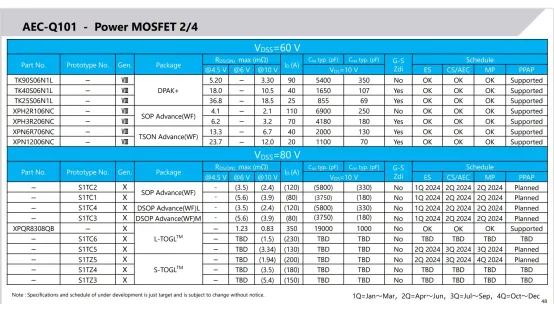
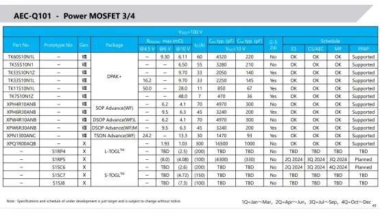
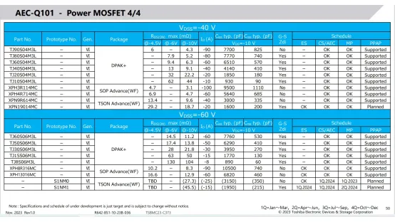
The above information is quoted from Toshiba's promotional PPT material: TSBMC24-C315, Sep. 2024 Rev1.0
SHANGHAI YCT ELECTRONICS GROUP CO., LTD
Business Phone: 86 (21)-51516111
Business E-mail:office@yctexin.com
Company Address: No.62, Lane 99 Chunguang Road, Shanghai, China
Landline
Scan and follow us
Get more electronic product informatio
©2024 SHANGHAI YCT ELECTRONICS GROUP CO., LTD. Powered by www.300.cn SEO Privacy Policy