Analysis of DCDC Buck Circuit
2024-10-11 09:00
Analysis of DCDC Buck Circuit
DCDC circuits are commonly used in our daily lives, but many people do not know what DCDC circuits are and how they work. Next, through this article, we will introduce the working principle of DCDC circuits.
DCDC circuit is a direct current to direct current circuit that converts a certain DC power source into a circuit with different voltage values. It is divided into boost circuit (Boost), buck circuit (Buck), and buck boost circuit (Buck Boost). In this issue, we will first introduce the voltage reduction circuit.
The step-down circuit and step-up circuit are mainly composed of inductors, capacitors, diodes, and switching devices. The voltage at both ends of the capacitor cannot suddenly change. Capacitors have the characteristics of conducting AC, blocking DC, conducting high frequency, and blocking low frequency; The current through the inductor cannot suddenly change, and the inductor has the characteristics of passing DC, blocking AC, passing low frequency, and blocking high frequency; A diode has unidirectional conductivity. According to the characteristics of inductors, capacitors, and diodes, different circuit designs can be used to achieve boost and buck functions.
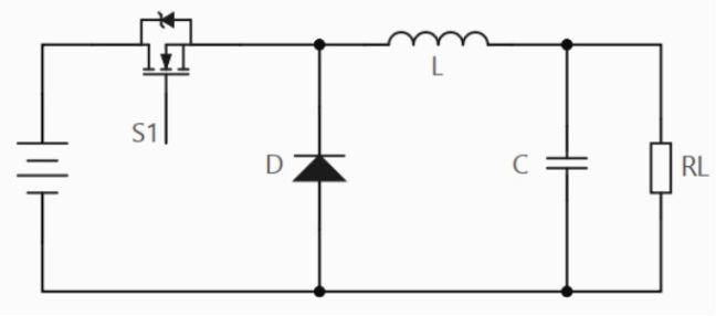
Step-down circuit
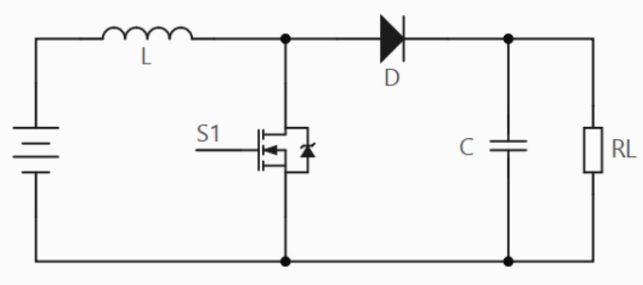
Boost type circuit
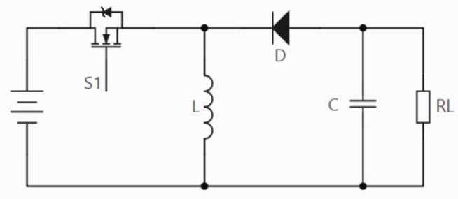
Voltage boosting circuit
Next, we will introduce the working principle of the step-down circuit: A step-down circuit is a non isolated DC converter with an output voltage ≤ input voltage.
When switch S1 is closed, diode D is cut off according to unidirectional conductivity, inductor L is magnetized and stored with energy, and the current flowing through the inductor linearly increases, while charging capacitor C and providing energy to load RL. At this point, the Vout voltage slowly increases. If S1 remains closed, the final Vout will be approximately equal to the Vin voltage (S1 has a loss voltage drop), and the current flow is shown in the following figure.
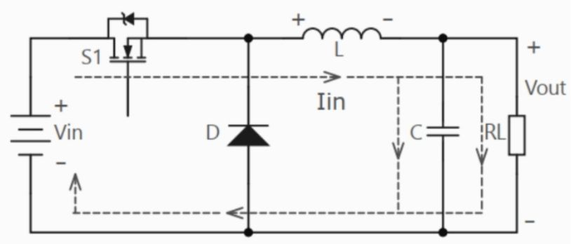
The switch is turned on, and the current flows in
When the switch S1 is turned off, the energy storage inductor L discharges through the freewheeling diode D, and the inductor current IL decreases linearly. If S1 remains turned off, Vout will eventually drop to 0V. The function of capacitors is to store energy, filter, and make the voltage at both ends of the load smoother. The current flow direction is shown in the following figure.
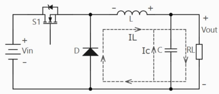
Switch disconnected, current flow direction
When the switch is turned on, the current passing through the inductor cannot suddenly change, and the current flowing through the inductor increases linearly. Since the circuit is continuously conducting (CCM working mode), it will not drop to 0. At this time, the diode is in the off state, so=0. When switch S1 is just turned on, the circuit current is relatively small, and the capacitor is still in a discharged state. When the circuit current reaches a certain value, the capacitor stops discharging and the power supply charges it.
When the switch is turned off, the inductor discharges, and the current on the inductor linearly decreases, causing the diode to conduct. Due to the switch being turned off, the circuit on the left side of the diode cannot conduct, resulting in=0; The capacitor is still in a charging state at this time, and the inductor charges the capacitor. When the circuit current gradually decreases to a certain value, the capacitor discharges. The current changes of each component in the specific circuit are shown in the following figure.
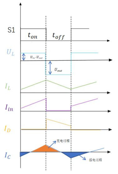
Analysis diagram of current of each component during the operation of the voltage reducing circuit
Duty cycle calculation of voltage reducing circuit:
(![]() -
-![]() )×
)×![]() ×
×![]() = 0
= 0
(The duty cycle calculation of the voltage reduction circuit is based on the voltage second balance of the inductor. Inductance volt second balance: Under steady-state conditions, the average voltage across the inductor during one switching cycle is zero.)
(![]() -
-![]() )×
)×![]() =
= ![]() ×
×![]()
![]() =
=![]() =
= ![]() =D
=D
Among them, D is the duty cycle of the voltage reducing circuit;![]() Turn off time for the switch;
Turn off time for the switch;![]() To determine the conduction time of the switch;
To determine the conduction time of the switch;![]() For the entire cycle time。
For the entire cycle time。
![]() =
= ![]() ×D,Therefore, controlling the duty cycle of the switching transistor can control the output voltage.
×D,Therefore, controlling the duty cycle of the switching transistor can control the output voltage.
As described above, a DCDC circuit is a direct current to direct current circuit that utilizes the charging and discharging of inductors, the unidirectional conductivity of diodes, and the on-off time of switches to achieve the desired voltage value. The above is the complete content of the DCDC Buck circuit analysis. Thank you for reading!


